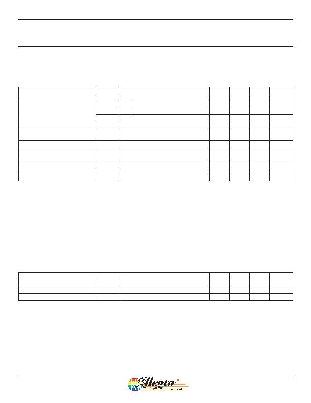
ELECTRICAL CHARACTERISTICS Valid at T
A
= 40癈 to 150癈, T
J
< T
J
(max), C
BYP
= 0.01 糉, through operating supply voltage
range; unless otherwise noted
Characteristics
Symbol
Test Conditions
Min. Typ. Max. Unit
Supply Voltage
1,2
V
CC
Operating, T
J
d 165 癈
3.0
24
V
Supply Current
I
CC(L)
-I1 B < B
RP
5
6.9 mA
-I2 B < B
RP
2
5
mA
I
CC(H)
B > B
OP
12
17
mA
Supply Zener Clamp Voltage
V
Z(sup)
I
CC(L)
(max) + 3 mA, T
A
= 25癈
28
V
Supply Zener Clamp Current
I
Z(sup)
V
Z(sup)
= 28 V
I
CC(L)
(max)
+ 3 mA
mA
Reverse Supply Current
I
RCC
V
RCC
= 18 V
1.6 mA
Output Slew Rate
3
di/dt
No bypass capacitor, capacitance of probe
C
S
= 20 pF
90
mA / 約
Chopping Frequency
f
c
700
kHz
Power-Up Time
2,4,5
t
on
25
約
Power-Up State
4,6,7
POS t
on
< t
on
(max) , V
CC
slew rate > 25 mV / 約
I
CC(H)
1
V
CC
represents the generated voltage between the VCC pin and the GND pin.
2
The V
CC
slew rate must exceed 600 mV/ms from 0 to 3 V. A slower slew rate through this range can affect device performance.
3
Measured without bypass capacitor between VCC and GND. Use of a bypass capacitor results in slower current change.
4
Power-Up Time is measured without and with bypass capacitor of 0.01 糉, B < B
RP
10 G. Adding a larger bypass capacitor would cause longer
Power-Up Time.
5
Guaranteed by characterization and design.
6
Power-Up State as defined is true only with a V
CC
slew rate of 25 mV / 約 or greater.
7
For t > t
on
and B
RP
< B < B
OP
, Power-Up State is not defined.
MAGNETIC CHARACTERISTICS
1
Valid at T
A
= 40癈 to 150癈, T
J
< T
J
(max); unless otherwise noted
Characteristics
Symbol
Test Conditions
Min. Typ. Max. Unit
2
Magnetic Operating Point
B
OP
5
80
G
Magnetic Release Point
B
RP
80
5
G
Hysteresis
B
HYS
B
OP
B
RP
40
110
G
1
Relative values of B use the algebraic convention, where positive values indicate south magnetic polarity, and negative values indicate north
magnetic polarity; therefore greater B values indicate a stronger south polarity field (or a weaker north polarity field, if present).
2
1 G (gauss) = 0.1 mT (millitesla).
Chopper-Stabilized, Two Wire
Hall-Effect Latch
A1244
3
Allegro MicroSystems, LLC
115 Northeast Cutoff
Worcester, Massachusetts 01615-0036 U.S.A.
1.508.853.5000; www.allegromicro.com
发布紧急采购,3分钟左右您将得到回复。
相关PDF资料
A1302KUA-T
IC SENSOR HALL EFFECT 3-SIP
A1323LLHLT-T
IC SENSOR HALL EFFECT SOT23W
A1351LKTTN-T
IC SENSOR HALL EFFECT 4-SIP
A1354KKT-T
IC SENSOR HALL EFFECT 4-SIP
A1356LKB-T
IC SENSOR HALL EFFECT 3 SIP
A1361LKTTN-T
IC HALL EFFECT SENSOR LN 4-SIP
A1374EKB-T
IC SENSOR HALL EFFECT PREC 3-SIP
A1422LK
IC SENSOR HALL EFFECT AC 4-SIP
相关代理商/技术参数
A1245LLHLT-I1-T
功能描述:IC HALL EFFECT LATCH SOT23-3 制造商:allegro microsystems, llc 系列:- 包装:带卷(TR) 零件状态:有效 功能:卡销 技术:霍尔效应 极化:南极 感应范围:4mT 跳闸,-4mT 释放 测试条件:-40°C ~ 150°C 电压 - 电源:3 V ~ 24 V 电流 - 电源(最大值):6.9mA 电流 - 输出(最大值):- 输出类型:开路漏极 特性:- 工作温度:-40°C ~ 150°C(TA) 封装/外壳:TO-236-3,SC-59,SOT-23-3 供应商器件封装:SOT-23-3 标准包装:3,000
A1245LLHLT-I2-T
功能描述:IC HALL EFFECT LATCH SOT23-3 制造商:allegro microsystems, llc 系列:- 包装:带卷(TR) 零件状态:有效 功能:卡销 技术:霍尔效应 极化:南极 感应范围:4mT 跳闸,-4mT 释放 测试条件:-40°C ~ 150°C 电压 - 电源:3 V ~ 24 V 电流 - 电源(最大值):5mA 电流 - 输出(最大值):- 输出类型:开路漏极 特性:- 工作温度:-40°C ~ 150°C(TA) 封装/外壳:TO-236-3,SC-59,SOT-23-3 供应商器件封装:SOT-23-3 标准包装:3,000
A1245LLHLX-I1-T
功能描述:IC HALL EFFECT LATCH SOT23-3 制造商:allegro microsystems, llc 系列:- 包装:带卷(TR) 零件状态:有效 功能:卡销 技术:霍尔效应 极化:南极 感应范围:4mT 跳闸,-4mT 释放 测试条件:-40°C ~ 150°C 电压 - 电源:3 V ~ 24 V 电流 - 电源(最大值):6.9mA 电流 - 输出(最大值):- 输出类型:开路漏极 特性:- 工作温度:-40°C ~ 150°C(TA) 封装/外壳:TO-236-3,SC-59,SOT-23-3 供应商器件封装:SOT-23-3 标准包装:10,000
A1245LLHLX-I2-T
功能描述:IC HALL EFFECT LATCH SOT23-3 制造商:allegro microsystems, llc 系列:- 包装:带卷(TR) 零件状态:有效 功能:卡销 技术:霍尔效应 极化:南极 感应范围:4mT 跳闸,-4mT 释放 测试条件:-40°C ~ 150°C 电压 - 电源:3 V ~ 24 V 电流 - 电源(最大值):5mA 电流 - 输出(最大值):- 输出类型:开路漏极 特性:- 工作温度:-40°C ~ 150°C(TA) 封装/外壳:TO-236-3,SC-59,SOT-23-3 供应商器件封装:SOT-23-3 标准包装:10,000
A1245LUA-I1-T
功能描述:IC HALL EFFECT LATCH 3SIP 制造商:allegro microsystems, llc 系列:- 包装:散装 零件状态:有效 功能:卡销 技术:霍尔效应 极化:南极 感应范围:4mT 跳闸,-4mT 释放 测试条件:-40°C ~ 150°C 电压 - 电源:3 V ~ 24 V 电流 - 电源(最大值):6.9mA 电流 - 输出(最大值):- 输出类型:开路漏极 特性:- 工作温度:-40°C ~ 150°C(TA) 封装/外壳:3-SIP 模块 供应商器件封装:3-SIP 标准包装:500
A1245LUA-I2-T
功能描述:IC HALL EFFECT LATCH 3SIP 制造商:allegro microsystems, llc 系列:- 包装:散装 零件状态:有效 功能:卡销 技术:霍尔效应 极化:南极 感应范围:4mT 跳闸,-4mT 释放 测试条件:-40°C ~ 150°C 电压 - 电源:3 V ~ 24 V 电流 - 电源(最大值):5mA 电流 - 输出(最大值):- 输出类型:开路漏极 特性:- 工作温度:-40°C ~ 150°C(TA) 封装/外壳:3-SIP 模块 供应商器件封装:3-SIP 标准包装:500
A12466
制造商:BACO Controls Inc 功能描述:
A1247
制造商:Hakko 功能描述:Tip,B,929 -2/939,903 Used With Soldering Stations